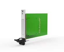
System PXI Express, 4 U, 18 gniazda, Gen2
 Najedź kursorem, aby powiększyć obraz, lub kliknij, aby go powiększyć.
System PXI Express, 4 U, 18 gniazda, Gen2
nr katalogowy: 14579-043
Obudowa typu desktop PXI Express do jednego kontrolera systemowego PXI Epress z maksymalnie 16 HP i 7 płytami PXI lub PXI Express o szerokości 4 HP.

Szczegóły
Zasoby
Item(s) Delivered
Powiązane akcesoria
Recommended Products
Dystrybutorzy w Twojej okolicy
Szczegóły
Zasoby
Item(s) Delivered
Powiązane akcesoria
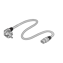
![Cable Schuko Plug - IEC]()
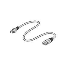
![mains cable]()
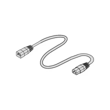
![mains cable]()
![mains cable]() Recommended Products
Dystrybutorzy w Twojej okolicy
Recommended Products
Dystrybutorzy w Twojej okolicy
Funkcje
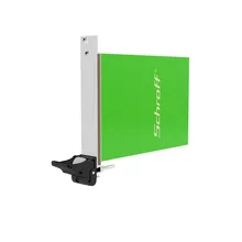
- Obudowa biurkowa PXI Express, 4 U, 84 km, z uchwytami i 19 wspornikami montażowymi
- Gniazdo systemowe PXI Express o szerokości 16 km, gniazdo czasowe PXI Express i 16 gniazda hybrydowe
- Przełączanie PCIe Gen 2 z czterołączającym (4x1) gniazdem systemowym
- Koncepcja wydajnego chłodzenia z niskim poziomem hałasu wentylatora, 50 w na gniazdo przy wzroście temperatury 15 tys.
- Przepływ powietrza z dołu do tyłu z wentylatorami sterowanymi temperaturą; zintegrowany moduł monitorowania podwozia (CMM)
- Wejście prądu zmiennego z przełącznikiem sieciowym z tyłu, przycisk zasilania z przodu (u góry) zewnętrzne wejścia/wyjścia zegara 10 MHz na tylnym panelu
Specyfikacje
Atrybuty produktu
Arkusz danych
Instrukcja instalacji / Arkusz instrukcji
Oprogramowanie sprzętowe
Delivery of this product includes the following item(s):
| Item | Opis | Ilość | |
|---|---|---|---|
| 1 | RatiopacPRO chassis with handles; 4 U, 84 HP, 355 mm deep; shielded; tip-up feet | 1 | |
| 2 | Front slot; IEEE guide rails, incl. ESD clips (ESD clips assembled at bottom front), for vertical boards (3 U, 160 mm deep) | 18 | |
| 3 | PXIe Backplane, 18 slots, System slot left | 1 | |
| 4 | PCIe 6 Lane Switch Module, PCIe Gen 2, mounted on backplane backside | 4 | |
| 5 | PCIe-PCI Bridge Module, PCIe x1 to 32-bit 33 MHz, mounted on backplane backside | 2 | |
| 6 | PXI Express Clock Module, PXI-1 & PXI-5 CLKs, mounted on backplane backside | 1 | |
| 7 | PXI Trigger Bridges, mounted on backplane backside | 2 | |
| 8 | Power supply 1200 W; wide range input 100 ... 240 VAC; output: 3,3 V / 80 A, 5 V / 36 A, 12 V / 40 A, - 12 V / 20 A; 5 V aux / 2 A | 1 | |
| 9 | 120 mm fans | 3 | |
| 10 | Chassis Monitoring Module, CMM | 1 | |
| 11 | Mains inlet connector with switch, filter and fuse | 1 | |
| 12 | Power push button | 1 | |
| 13 | External 10 MHz REF clock output via BNC connector | 1 | |
| 14 | Optional 10 MHz REF clock source via BNC connector | 1 | |
| 15 | Cable harness to connect all system components | 1 |


Poniżej znajduje się lista autoryzowanych dystrybutorów, którzy aktualnie mają ten produkt na stanie:
| Dystrybutor | Ilość | Data dostępności w magazynie |
|---|
*The price shown is the per piece price and does not include VAT. Depending on local conditions, packaging and freight charges might not be included. Where these charges should be part of the total price, they are included in the quote. The price given is a non-binding recommended retail price (RRP), which is the nVent list price. The final sales prices of local distributors may vary. Quotations requested or generated on SCHROFF.nVent.com are only valid for commercial customers (B2B). The lead time displayed above is an estimate for this item to be dispatched from an nVent Schroff facility. Transit delivery times are not included in this estimate, as transit time may vary, depending on delivery address, parcel dimensions, and other factors. Cut-outs and modifications placed in non-recommended areas ("collision detected") for configured products may be subject to additional engineering and/or design costs, which may increase initially quoted prices.
- Ostrzeżenie
- Produkty nVent powinny być instalowane i używane wyłącznie zgodnie z instrukcjami i materiałami szkoleniowymi nVent. Instrukcje są dostępne na stronie www.nvent.com oraz u przedstawiciela działu obsługi klienta firmy nVent. Nieprawidłowa instalacja, niewłaściwe użycie, niewłaściwe zastosowanie lub inne nieprzestrzeganie instrukcji i ostrzeżeń nVent może spowodować nieprawidłowe działanie produktu, uszkodzenie mienia, poważne obrażenia ciała i śmierć i/lub utratę gwarancji.