 Najedź kursorem, aby powiększyć obraz, lub kliknij, aby go powiększyć.

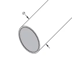
nVent ERICO Cu-Bond Round Conductor
For decades, nVent ERICO has provided the market with high quality copper-bonded ground rods. nVent ERICO has taken that same concept in ground rods and made this into a revolutionary new grounding conductor. The core of the nVent ERICO Cu-Bond Round Conductor is a low carbon steel grade for improved flexibility in the field. The steel core is plated with nickel then electro-plated with a coating of copper. This electro-plating process helps ensure a long-lasting molecular bond between the copper layer and the steel.
The steel core of the conductor provides theft-deterrent benefits, making the conductor difficult to cut with hand tools. With this steel core, nVent ERICO Cu-Bond Round Conductor is a cost-effective alternative to 100% copper conductor. The copper surface of the conductor provides high conductivity and corrosion resistance properties.
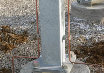
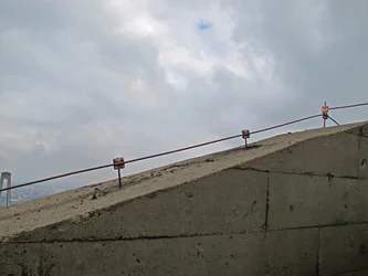
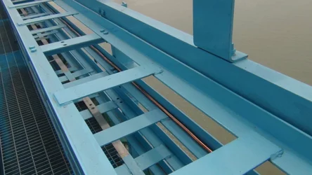
Above grade, the unique properties of nVent ERICO Cu-Bond Round Conductor make it ideal for both horizontal and vertical placement. The conductor is well-suited as a lightning protection conductor when applied in accordance with the IEC 62305-3 Edition 2.0 standard.
In the utility industry, the product can be used as a distribution down-lead conductor or as part of a bonding kit for substation fences or equipment ground risers back to the grid. In telecom applications, the product can be used to connect an equipment ground to the ground grid, as a riser (down-lead) for towers, or as a grounding conductor for datacenter mesh bonding. They are also well suited for rail applications such as trackside bonding conductors and stray current conductors, grounding kits for trackside equipment, electrical traction power, as well as in substation, wayside shelters, and communication antenna equipment.
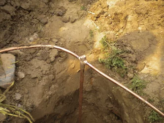
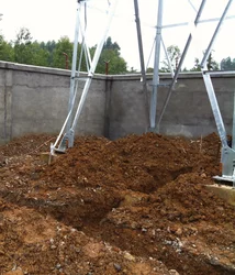
Below grade, nVent ERICO Cu-Bond Round Conductors are ideal as earthing and bonding conductors where copper theft may occur. They may be used as a buried ground grid conductor or electrode for wireless telecom towers, power distribution and transmission grounding in utility substations, large scale ground mount solar farms, petro-chemical and mining infrastructure in industrial facilities, and railway applications. The conductor also can be used as an interconnecting grounding conductor between wind towers or as a grounding grid at the base of a wind tower.
Funkcje
- Theft-deterrent; steel core is hard to cut with hand tools
- Cost-effective; copper bonded to a steel core minimizes the amount of copper in the cable
- Superior corrosion resistance; application life of typically 30-40 years in most soil conditions
- Copper-bonded coating will not crack or tear when the conductor is bent
- High resistance to corrosion and provides a low-resistance path to ground
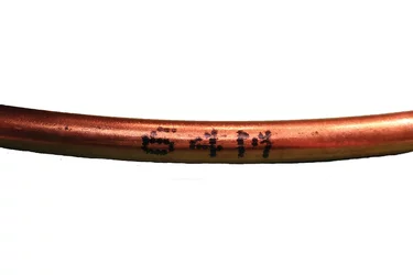
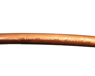
- nVent ERICO Cu-Bond Round Conductor is marked every meter (3.28') for easy measurement in the field
- Meets the requirements of IEC® 62305-3 Edition 2 and IEC/EN 62561-2 for lightning protection applications
- nVent ERICO Cu-Bond Round Conductors are UL certified to IEC® 62561-2
Specyfikacje
| Zestawienie fizycznych rozmiarów przewodów | ||
| Rozmiar przewodu | Przybliżona średnica | Przekrój |
| 25 mm² | 6,76 mm | - |
| 35 mm² | 7,65 mm | - |
| CBSC8 | 8,00 mm | 50,27 mm² |
| 50 mm² | 8,89 mm | - |
| CBSC10 | 10,00 mm | 78,52 mm² |
| 70 mm² | 10,69 mm | - |
| 95 mm² | 12,47 mm | - |
| CBSC13 | 13,20 mm | 138,07 mm² |
| CBSC14 | 14,20 mm | 158,90 mm² |
| 120 mm² | 14,22 mm | - |
| CBSC16 | 15,70 mm | 199,84 mm² |
| 150 mm² | 15,75 mm | - |
| 185 mm² | 17,65 mm | - |
| CBSC18 | 17,70 mm | 243,27 mm² |
| Porównanie przewodności | ||||
| Nr części | AWG (Ω/km) | CBSC - rezystancja w odniesieniu do długości | mm² (Ω/km) | CBSC - rezystancja w odniesieniu do długości |
| CBSC18 | 1/0 AWG | 118,52% | 50 mm² | 110,82% |
| 2 AWG | 74,54% | 35 mm² | 77,57% | |
| CBSC16 | 2 AWG | 102,20% | 35 mm² | 106,36% |
| 4 AWG | 64,27% | 25 mm² | 75,97% | |
| CBSC14 | 2 AWG | 137,78% | 25 mm² | 102,42% |
| 4 AWG | 86,65% | 16 mm² | 65,55% | |
| CBSC13 | 2 AWG | 134,46% | 25 mm² | 99,95% |
| 4 AWG | 84,56% | 16 mm² | 63,97% | |
| CBSC10 | 4 AWG | 132,25% | 16 mm² | 100,05% |
| 6 AWG | 83,17% | 10 mm² | 62,53% | |
| CBSC8 | 6 AWG | 107,85% | 16 mm² | 129,73% |
| 8 AWG | 67,83% | 10 mm² | 81,08% | |
| Prąd topnienia Irms (kA) - IEEE® 837 Załącznik C | |||||||
| Typ przewodu Miedziowany, rdzeń stalowy, pręta | CBSC8 | CBSC10 | CBSC13 | CBSC14 | CBSC16 | CBSC18 | |
| Przekrój przewodu w mm2 | A | 50.265 | 78.52 | 138.07 | 158.903 | 199.84 | 243.27 |
| Początkowa temperatura przewodu w °C | Ta | 40 | 40 | 40 | 40 | 40 | 40 |
| Czas przepływu prądu w sekundach | tc | 2 | 2 | 2 | 2 | 2 | 2 |
| Maksymalna dopuszczalna temperatura w °C | Tm | 1084 | 1084 | 1084 | 1084 | 1084 | 1084 |
| Współczynnik termiczny rezystywności przy temperaturze referencyjnej Tr | ar | 0.00378 | 0.00378 | 0.00378 | 0.00378 | 0.00378 | 0.00378 |
| Rezystywność przewodu uziemiającego przy temperaturze referencyjnej Tr in m&-cm | rr | 8.621 | 8.621 | 8.621 | 8.621 | 8.621 | 8.621 |
| 1/a0 lub (1/ar) – Tr w °C | K0 | 245 | 245 | 245 | 245 | 245 | 245 |
| Współczynnik pojemności cieplnej w dżulach/cm3/°C | TCAP | 3.846 | 3.846 | 3.846 | 3.846 | 3.846 | 3.846 |
| Przewodność materiałowa | % | 24.5 | 20.4 | 18.8 | 15.9 | 16.3 | 17.7 |
| Wyliczenie prądu topnienia | ß | 84.73 | 84.73 | 84.73 | 84.73 | 84.73 | 84.73 |
| I | 4.79 | 7.48 | 13.16 | 15.15 | 19.05 | 23.19 | |
| I90% | 4.31 | 6.74 | 11.84 | 13.63 | 17.14 | 20.87 | |
| I80% | 3.83 | 5.99 | 10.53 | 12.12 | 15.24 | 18.55 | |
Broszura
Instrukcja instalacji / Arkusz instrukcji
Katalog
Certyfikaty
- Ostrzeżenie
- Produkty nVent powinny być instalowane i używane wyłącznie zgodnie z instrukcjami i materiałami szkoleniowymi nVent. Instrukcje są dostępne na stronie www.nvent.com oraz u przedstawiciela działu obsługi klienta firmy nVent. Nieprawidłowa instalacja, niewłaściwe użycie, niewłaściwe zastosowanie lub inne nieprzestrzeganie instrukcji i ostrzeżeń nVent może spowodować nieprawidłowe działanie produktu, uszkodzenie mienia, poważne obrażenia ciała i śmierć i/lub utratę gwarancji.

